
ben at davies . net Home mirror OTA mount dimensions and specifications focuser end
Flotation Cell
The usual collimation arrangement for primary mirror cells is to have 3 adjustable spring tensioned bolts spaced at 120 deg. The mirror is aimed at the secondary mirror by adjusting these bolts up and down independently.
I see 2 difficulties with this design:
1) The 120 deg spacing makes aiming the mirror a pain, and
2) The mirror is not fixed in space relative to the secondary..
Over a number of collimation cycles using this standard arrangement, as the bolts adjust the cell up and down to aim the mirror, the cell can move towards or away from the secondary causing the focal plane to move a bit. Most of us will have a tendency to turn the bolts one way more than the other. The focuser will simply adjusts to the new main mirror location. So using this cell, it is a good idea to leave the focal plane a little higher than absolutely necessary to compensate for movement of the 100% FOV. So how much does an extra 1/4" cost you in terms of FOV? Depends on the f ratio. For f6, it's around 7%; for f3.5, around 18%. If you want to get the largest FOV for a given diagonal size, you need to know where the mirror is. Because designing the layout of the optics involves a tradeoff between diagonal size and 100% FOV you might be able to take the gain in a smaller diagonal.
Secondly, the optical axis of the mirror can move away from the telescopes geometrical axis (side to side). This can affect your ability to place the focused image right in the center of the eyepiece. If the image is off near the edge of the field stop, it is noticed and fixed. But if it is off by 10% it might never be noticed.
All this is obviously less of a problem in a telescope that doesn't travel around in the trunk of a car.
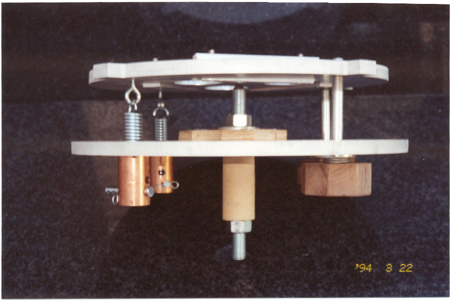
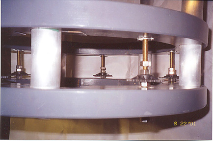
Center Pivot Floatation Cell
These deficiencies can be remedied with a modest amount of extra effort when building the cell. The concept is illustrated above in the sketches and pictures. They show a double plate cell which maintains the usual 'multiple of 3' flotation point mirror supports. The bottom plate is attached to the OTA. The top plate is attached to the bottom plate and rolls on a center pivot post that is fixed to the lower plate. This makes it possible to only have 2 collimation bolts which are at 90 degrees to each other. Each is opposed by a tension spring which holds the plates together. The top plate can then roll and yaw on the pivot point for aiming at the secondary but has no other freedom of movement with respect to the geometric axis of the telescope. It cannot move towards or away from the secondary and it cannot move from side to side.
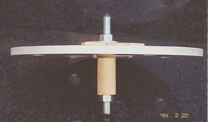
It is also possible to configure this cell so that the mirror is movable back and forth along the optical axis. The threaded rod can be adjusted up or down, moving the mirror. This movement is obviously limited by the spring length and tension.
Since the center of the cell is occupied by the post, I use 3 small fans rather than one large one.
MORE IMAGES OF THE CENTER PIVOT CELL
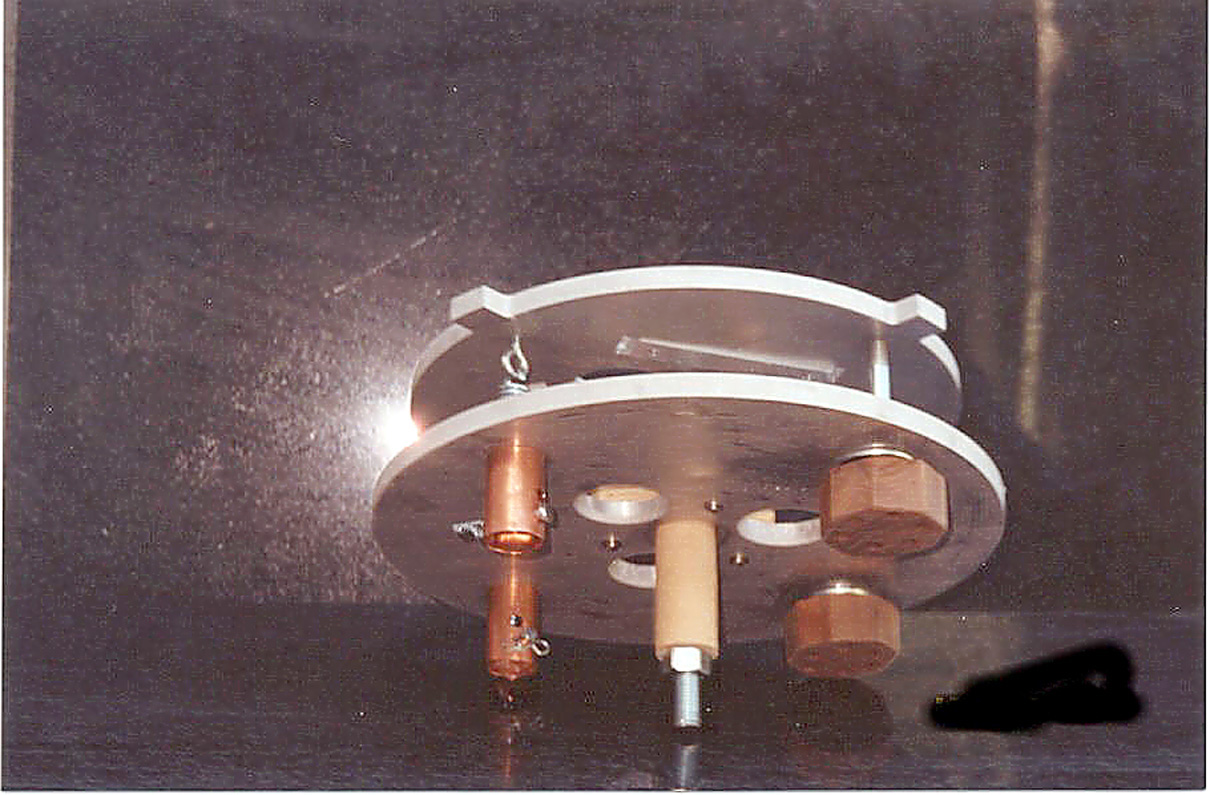
Bottom Plate and pivot - detached
Movable Primary
Adjusting the distance between the primary and the secondary
Without mirror cell and chain. The upper ring is fixed to the tubes and the lower ring moves on Teflon sleeves. The T-nut is epoxied to the upper ring.
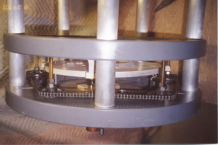
The chain drive turns all sprockets equally and moves the main mirror towards or away from the secondary mirror to change from visual observing to photography.
OTHER MIRROR CELL SCHEMES
This turns out to be the wheel I reinvented.
After working out the details of this center pivoting platform and building it, I recognizeded the secondary mirror aiming scheme in Texereau's How to Make a Telescope

Notice here that he has done the same thing that I have, except that the center post pulls down on the top plate (to keep the same terminology) instead of pushing against it. He uses 3 collimation screws and as I see it one must be simultaneously loosened as another is tightened. My two-bolt right angle arrangement with opposing springs is preferable. In Texereau's cell the forces are inverted and the springs are located in compression between the plates.
Here is the modified Texereau arrangement adapted as a primary cell.
This will work just as well as mine, and has the advantage of being more compact. It has the disadvantage that the mirror's weight is supported on a compression spring. So that spring would need to be quite stiff in order to work. (Steve Lee rests the cell on springs on his imaging telescope and it works for him.) I don't know what would be used for the center post, maybe a auto valve solid lifter.
THE USUAL SUSPECT
The standard 3 point 120 degree cell can itself be improved upon to convert it to a 90 deg collimation arrangement.

A, B, and C are the bolt locations on 3 corners of a square instead of at 120 deg. B remains fixed. As A is adjusted up and down, the line BC acts as a hinge and similarly AB is the hinge when C is adjusted. So we have 2 orthogonal collimation bolts. B would only be moved to adjust the distance between the primary and the secondary. The center is left unobstructed to accommodate a single fan. The focal distance still changes as the mirror is calumniated, but the motion is limited by not adjusting with B.
© 2001 Ben Davies