Home mirror OTA mount dimensions and specifications mirror cell
updated 2/13/03
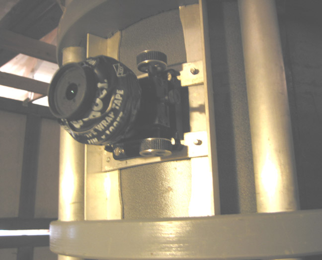
The black tape on this eyepiece conceals solder wire. By increasing the weight of the lighter eyepieces, the tube's balance is maintained.
Many decisions made at the focuser end involve trade-offs. There are more variables than there are equations so to speak, so the final answers are arrived at by iteration. For me there were 2 tools that were indispensable in balancing the competing values: Dale Keller's Newt.exe and a full size layout.
What you want to achieve is a fully illuminated plane sufficiently large for your purposes, high contrast, and no stray light in the focuser.
Premise: That the fully racked in drawtube should not intrude on the true field of view of the primary, and that all calculations of where to locate the focuser should begin with this.
THE FOCUSER
First choose a particular focuser. Just do it. The process of iteration starts here. If we work through the process and find that there is no way to make this choice work, we come back and start over. The very low profile ones are out of favor because of the difficulty keeping stray light out of the image. "I am not a fan of ultra short focusers anymore." - Mel Bartels.
I have a JMI DX2 and that seems to be a popular and reasonable choice. Measurements are based on the focuser's dimensions and you have to know them. JMI has a nice table of specifications, so that you don't actually have to buy it in order to have the dimensions you need and start planning. Iteration gets expensive when real parts are involved.
THE EYEPIECES
It is hard to think about eyepieces early in the game, but you must. At the least you will need to know the lowest magnification eyepiece as it has the widest field of view. It is the boundaries of this field of view in the OTA that determines the limit for the fully racked in drawtube. Also, the lowest useful magnitude is based on exit pupil size for the scope's f-ratio. Choose an exit pupil size based on your pupil size. Or choose 7mm if you want to be inclusive.
Then: longest focal length eyepiece (lowest magnification) = exit pupil size x f-ratio. In my case f-ratio is 6.02 and my pupil size is 5mm, so 6.02 x 5 = 30.1. Since money is no object and we know that the optics are the last place to skimp, let's choose a 31mm Nagler type 5. Tele-Vue has a website giving the needed dimensions: AFOV, field stop, location of the image plane.
THE APERTURE
My primary mirror diameter is 12 7/16", but the front aperture is larger than 12 7/16" by the true field of view of the eyepiece in use. Dale Keller, Richard Combs and others use formula which gives an approximation of the TFOV.
TFOV = Apparent FOV / magnification
AFOV is from Tele-Vue and the magnification is focal length of the main mirror / focal length of the eyepiece
TFOV=82 / 61 = 1.34deg
Tele-Vue calculates the TFOV using the formula:
True field of view (degrees) = (eyepiece field stop diameter / telescope focal length) x 57.3
TFOV=42 / 1902 * 57.3 = 1.27 deg
The Tele-Vue formula yields a smaller TFOV and this is likely more accurate since we can assume that Tele-Vue knows their lenses, but I still use the first for decisions on tube diameter since it is wider and will give some leeway in the vignetting department. The difference amounts to about 1/16" of tube radius at the focuser so we're not talking about a huge difference anyway.
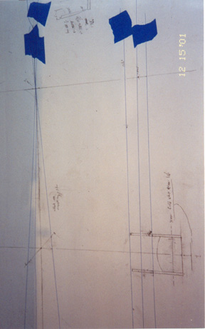
Layout: I found that the best materials for the full size layout are a sheet of white p-lam (Formica) and sewing thread. The laminate is flat and stiff and the thread makes fine uniform lines. Use masking tape to hold the ends down.
So looking at the trig in the figure above, we could make the tube 14" (at the focuser) and have no vignetting of the TFOV. But this is not wide enough. There can be convection currents hugging the wall of the tube and we must make it larger to keep the offending currents away from the light which will be forming the image. So the tube diameter becomes 15". Fine, but by enlarging the tube to accommodate currents, the focuser is pushed 1/2" farther away from the diagonal than is absolutely necessary. This is going to take care of itself when we consider the focuser drawtube length.
OPTICAL DISTANCES - LOCATING THE FOCUSER
Now there is enough information do go to work on the optical distances and focuser placement. This is the JMI DX2 focuser with 2, 2.5, and 3" drawtubes. Given that we don't want the drawtube to penetrate into the TFOV, the question we want to answer is: Where does the base of the focuser go in relation to outside wall of the tube?
From JMI's table of specifications: for the various drawtubes
JMI information in italics
Drawtube Length (L) = 2" 2.5" 3"
Minimum Height H (+ 1/8")1 = 1.725 1.725 1.725
Formula Constant X = .41 .41 .41
Maximum Extension E (L + X) = 2.41 2.91 3.41
Drawtube Travel (E - H) = 0.81 1.31 1.81
Maximum Penetration (L - H) = 0 .275 0.775 1.275
Tube Thickness 1/16" = 0.0625 0.0625 0.0625
OTA diameter 15 1/16"
Focuser offset2 (from 15" dia) = -.225" +.275" +.775" (negative number is into the tube)
1. NOTE: JMI gives 1.6 as the minimum height (H). This assumes that the adjusting set screws are not used. But my experience has been that in collimating the optics, they get extended some amount, so I give an extra -1/8" to the focuser offset because we are designing so close to the limits. Negative numbers of focuser offset indicate the base of the focuser is inside the tube wall.
2. Place the end of the fully racked in drawtube at the edge of the TFOV. In this case at a radius of 7". Now add the maximum penetration and subtract the tube outside diameter (7 1/2") 7+.275-7.5= -.225 for the 2" drawtube.
H is 1.725" MP (of the 2" drawtube) is .28" DT is .81" and Spare In Travel is .5" (that means that the image plane - the focal point - is located 1/2" above the top of the focuser.)
So the radius from the centerline of the optical tube assembly (OTA) to the edge of the True Field of View is 1/2 of 12 7/16 plus .76" or nearly 7". To this we are going to add the Maximum Penetration so as to keep the fully racked in tube out of the field of view. For a 2" drawtube, we add .28" and have a 7.28" radius. We should enter into Newt a tube diameter of 14.56 " 2* (7 + .28). The tube thickness for the moment is 0. So the total distance from the center line of the OTA to the image plane is 9.5":
Location of the image plane:
Now use Newt.exe. Under Specifications, it wants:
Tube inside diameter and the wall thickness -> 15 3/16" and 1/16". Here I use 151/4" and 0 because Newt doesn't like 1/16" walls
Focuser Height -> radiusTFOV (7") + Maximum Penetration (.275") + Height of the focuser body H (1.725") - Radiusota (7.625") = 1.625"
Spare in travel -> 1/2"
Additional height for camera -> This is another whole set of variables. You have front of the camera body to the film plane, flip mirrors, front of the mount to the plane of the ccd, filter wheel thickness. If you were to use a Starlight express MX-7 and a True Technologies filter wheel, use 2". For visual use 0.
Keep in mind, that we were only actually going to use this tube diameter if it is 15" or larger because of tube air current considerations. For the 2" drawtube length offset is less than 0" so the focuser base will have to be mounted inside the OTA by approx 1/4".
I should comment on "spare focuser in travel". This is a phrase coined by Keller and refers to the height of the image plane above the focuser tube when fully racked in. Commonly the recommendation is to use 1/2" here. Most eyepieces want the image plane at or below the shoulder that mates with the focuser tube. But not some of the Tele-Vue Naglers. The 31mm type 5 wants the image plane 3/8" above the shoulder. Ditto the 22mm type 4. So, by planning on 1/2" of in travel we wind up with 1/8' of spare travel. This is just right for me, because I have a mirror cell that doesn't move when I collimate it. And I have an adjustable mirror, so no problem. Less forgiving designs, however, might want a little more spare in travel.
Using the above parameters, Newt returns a 100% angular field of view of .4951 degrees and 6436. inches. This is quite large and we can move on to consider the next longer draw tube. The advantages of a longer tube are less chance of stray light getting to the eyepiece and more throw for focusing different eyepieces.
If we look at this drawtube in terms of a ccd and add in 2" for camera height, the 100% field is .2088". This is smaller than the MX-716's required area of .318", so this doesn't work for the ccd. It will need a larger diagonal mirror.
We have located the focuser in relation to the center of the tube. It is as close as it can get without obstructing the T FOV and consequently the 100% image plane is as large as it can be for a given size diagonal. Now, using Newt, play with different size diagonals until both the % obstruction and image size are satisfactory. Keep the diagonal size under 20% for good contrast and the 100% illuminated at or above 1/2 degree, or about the angular size of the full moon. A good list of available diagonal mirror sizes can be found at Newport Glass.
Plugging in the other drawtube lengths and using a 2.14" diagonal:
Drawtube Length |
location of focuser base |
Focuser height (for Newt) | + 2" for camera |
100% plane degrees |
100% dia inches |
75% plane degrees |
75% dia inches |
2" |
-.225 |
1.625 | no |
.457 |
.594 |
1.08 |
1.41 |
2" |
0 |
1.85 | no |
.425 |
.553 |
1.07 |
1.085 |
2.5" |
.275 |
2.125 | no |
.386 |
.502 |
1.054 |
1.391 |
3" |
.775 |
2.625 | no |
.3146 |
.409 |
1.025 |
1.333 |
2" |
-.225 |
1.625 | yes |
.14 |
.182 |
na |
na |
2.5" |
.275 |
2.125 | yes |
.064 |
.083 |
na |
na |
3" |
.775 |
2.625 | yes |
.013 |
.016 |
na |
na |
So, the 2.14" diagonal works for visual use, but not for the ccd
Repeat the process for a 2.37" secondary.
Drawtube Length |
location of focuser base (relative to tube wall) |
Focuser height (to Newt) | + 1.95" for ccd (to Newt) |
100% plane degrees (from Newt) |
100% dia inches (from Newt |
75% plane degrees (from Newt) |
75% dia inches (from Newt) |
2" |
-.225 |
1.625 | no |
.6637 | .8627 | 1.274 | 1.656 |
2" |
0 |
1.85 | no |
.6329 | .8226 | ||
2.5" |
.275 |
2.125 | no |
.5948 | .7732 | ||
3" |
.775 |
2.625 | no |
.5249 | .6822 | ||
2" |
-.225 |
1.625 | yes |
.354 | .4602 | 1.154 | 1.5 |
2.5" |
.275 |
2.125 | yes |
.2802 | .3642 | 1.125 |
1.46 |
3" |
.775 |
2.625 | yes |
.2052 | .2668 |
My Starlight Express MX716 Sony ccd chip is .318" diagonal measure, so the 2.37" diagonal with 2 1/2" drawtube works both for visual and for ccd
CHOOSE A DIAGONAL MIRROR
So looking at the above tables, the 2.5" drawtube with a 2.37" diagonal works for both visual and ccd imaging. However. Look at the values in Newt for distance from "mirror face to focuser hole". Without the camera, it is 64.595". With the camera it is 62.406. You cannot do both well unless you have a movable primary or a sliding focuser.
IS THERE ANY REAL SIGNIFICANCE TO ALL THIS?
Yes, there is.
I have never seen anyone admit to worrying about the length of the focuser drawtube and take it into account as we just have. But suppose we had used somebody's rule of thumb and arbitrarily arrived at the 15" tube diameter. Then we pick a JMI DX2 with a 3" drawtube because it seems popular. It appears that this is practically the same place we have arrived at anyway with less fuss. But look at what has happened. When mounted on the 15" tube wall, this drawtube is 2.31" od. and it projects into the TFOV by .775" when fully racked in. The area of the 2.14" diagonal is 3.6 sq inches. The area obscured by the drawtube is 1.7 square inches - about a 50% increase. This additional blockage of the light path changes the primary obstruction from 17% to 23%.
These numbers are generated for a f6 focal ratio. The situation worsens as the focal ratio goes down because the light cone has a steeper angle.
.
TUBE SIZE
I started out assuming that the focuser was just going to mount on the tube wall, but it turns out not be so that straightforward. We've located the TFOV at 14". If the tube is made 14", thermal currents which hug the tube walls will distort the image. So we need 1/2 inch of radius past the TFOV. Or a 15" tube. If the focuser were mounted at 15" and the 1/2 degree image plane maintained, the diagonal mirror must get larger, diminishing contrast. Not so much larger, but we don't give up anything we don't have to.
So we need a mechanical way to mount the focuser inside or outside the tube wall.
BAFFLING THE TUBE
After reading up on all the opinions I could find, I decided not to baffle the tube. See the links on the title page. I did a full size layout of the focuser end and extended the tube to the point (both ways) where light could not directly enter the field stop of the longest eyepiece. Then I lined the tube with black velvet painted with Krylon ultra flat black. That's it.
That's it except for one baffle at the focuser hole. I took a cardboard tube 1/4" larger than the od of the focuser drawtube and mounted it over the focuser hole between the tube wall and the TFOV. Using sandpaper, the outside end of the cylinder in made to fit the id of the OTA and the inside end is made to fit the circumference of the TFOV. This baffle tube is lined with the velvet. With it in place, no matter where the end of the drawtube is, there is maximum stray light shielding for the eyepiece.
THE TUBE SURFACE:
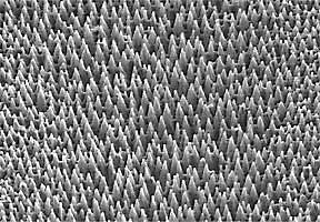
This is from a web page which is about light traps, but has nothing to do with low cost. However, it looks like velvet to me. Or sandpaper. There was a test made on painted sandpaper: It actually performs rather well.
I did some subjective (shine a light, look at the reflection) tests on a number of surfaces. Garnet paper painted black, sanded aluminum sheet painted black, black velvet, black velvet painted black.
I also had the idea that I could punch an aluminum sheet with a matrix of small closely spaced holes, flip the sheet over and punch back the other way between the holes. This leaves a saddle surface with (almost) all angles of reflection leading into the holes. Also, the sheet will wind up being spaced away from the telescope's tube - plastic laminate in my case - giving a chimney for thermal currents to be exhausted. I did a small sample and was disappointed in the reflectivity. The ridge of the saddle are too broad. It would need to be a crisp line to be effective. I do still like the idea of a chimney, but don't see a way to make it work.
Anyway, by far, the least reflective surface was black velvet painted flat black and this is what I use.
THE PAINT: What paint is best to coat the walls with? What is needed is to cover the surface with a non reflective coating which absorbs well in both visible and infrared.
Krylon's ultra flat black spray paint has an emissivity of .97
Zynolyte 1200 deg paint with an emissivity of .94
Anodized black aluminum by comparison has an emissivity of .88
So I paint the inside of the focuser draw tube and the spider vanes with the Krylon
see An emissivity primer.
see Emissivity of common materials
see emissivity of painted sandpaper
emissivity of a black painted aluminum disc
MJ Perslky Review of black surfaces for Space Born Infrared Systems
the blackest black surface photo
3M used to make a paint Nextel 3101c10 which tests better than Krylon ultra flat, but the brand was sold and I can't find it.
Daniel Ferene found it - Nextel Velvet Coating, and passed the information along. Ouch! $169 a liter +shipping (from Calif).
http://astro.umsystem.edu/atm/ARCHIVES/JUN98/msg01073.html an opinion on where 811-21 might be
http://masterweb.jpl.nasa.gov/reference/images/paints/Best%204%20paints%20MWIR.gif 1602 is Krylon Ultra Flat 1601: is Krylon Glossy: 17038 is Testors water base gloss black.
MECHANICAL COLLIMATION
 centering the spider's
hub
centering the spider's
hub
 centering the mirror
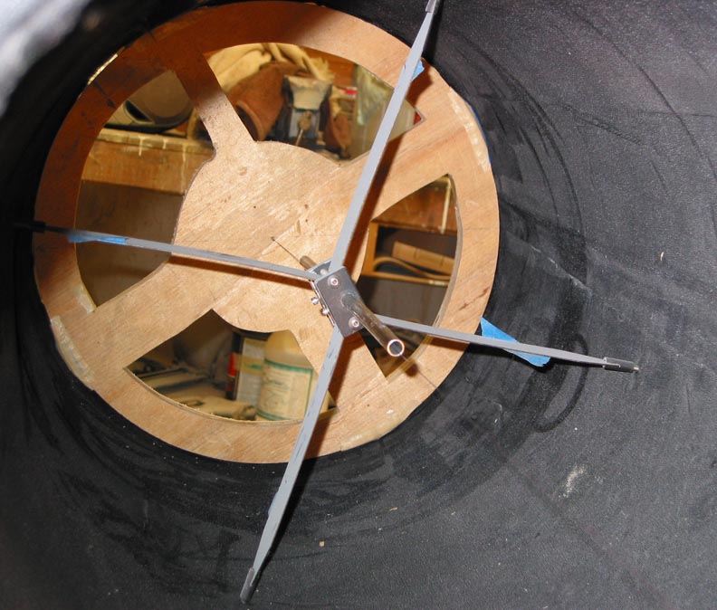
I use a offset vane spider with a glue-on secondary mirror from Gary Wolanski. The offset vane design is pretty much as described by Texereau on page 121 of How to Make a Telescope and is quite rigid.
A serious disadvantage of the glue-on mirror is that it is pretty much impossible to accurately place the mirror so that it's center is at the center of the holder shaft. Here is how to align the mirror:
1. Install the spider. Take care that the vanes on opposite sides are parallel to each other.
2. Make a 3/4" plywood disc to fit tightly in each end of the OTA. Drill a very small hole (thread size) at the offset center and one at the end each of the axes. Draw a circle on each disk the size of the minor axis of the secondary, centered on the offset center already marked.
3. Insert a tube into the spider in place of the shaft which holds the mirror holder
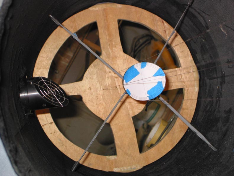
4. Pull a thread between the 2 offset centers through the tube. This is the mechanical axis of the OTA. Adjust the spider so that the tube is aligned with the axis. Remove the tube. Put a laser collimator into the focuser and square up the focuser. Remove the thread.
5. Pull 4 threads between the holes drilled into the plywood disks and check the focuser alignment again.
6. Tape a paper template on the face of the secondary mirror made from a cutout of page 284 of The Dobsonian Telescope (Kriege and Berry). This locates the major and minor axes. Now insert the secondary assembly into the spider and adjust the spider so that the edges of the mirror are aligned with the thread at the major and minor axes.
7. Using the laser pointer into adjust the focuser to aim at the major axis of the secondary. Then slide the mirror up or down so that the laser points to the center of the mirror. Remove the paper template and adjust the diagonal to aim at the center of the bottom plywood disk (not the offset center.) Remove the plywood disk and use the laser to position the primary mirror in the center.
Now the mechanical and optical axes are pretty well aligned and you can run through whatever optical collimation procedures you like to use.
©2002-3 Ben Davies