

Home mirror mirror cell-movable mirror mount dimensions and specifications focuser end
CANTILEVER TUBE ASSEMBLY
Why straight tubes instead of a triangulated truss?
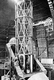
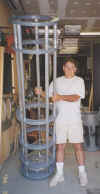
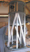
The 100" Hooker Telescope at Mt Wilson 1917 The 12.5" at my house In the end, the cantilever needed bracing
This assembly makes it very easy to find the geometrical axis of the telescope anywhere along the length of the OTA. The 3 sections (focuser end, declination axis box, and mirror end are independently adjustable so that the telescope can be rebalanced as new stuff (such as a ccd) is added. This tubular arrangement also makes it possible to easily move the main mirror and cell along the axis so as to change the focus location. The straight, stiff tubes make alignment more straightforward. Also, this whole tube, focuser and mirror assembly will drop into different mounts. One is a permanent equatorial horseshoe mount up at the farm and another is a John Dobson style altitude-azimuth mount for traveling. The entire tube assembly rotates in the mount to make the eyepiece more accessible. The third ring down is a little larger than the rest and has hard nylon bearing points that bear on 25 gauge galvanized sheet metal veneer on the mount. The forces normal to the OTA are taken up by 8 ball bearing assemblies that bear on 18 ga sheet metal strips attached to the outside circumference of the rings. There are 4 sets of bearings at the top of the declination box and 4 at the bottom.
The tube: 85 lbs with mirror cell, 15.25" id, 20"od, 79 3/4" length The 6061 aluminum tubes are 1/4" wall x 1 1/2" dia.
The mirror and cell are attached to the bottom ring which slides up and down the tubes on Teflon bearings. The motion is controlled by 5 threaded rods.
The ring - 1 of 6
High Friction Vibration Damping Pads Assembling the tube