HOME mirror mirror cell-movable mirror OTA dimensions and specifications drives observatory mechanical ben at davies . net
drawing of the 200" Hale by Russell W Porter
 my 'Pale Hale'
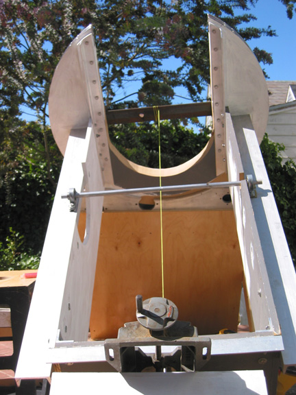 Aligning
the dec and ra axes
Aligning
the dec and ra axes
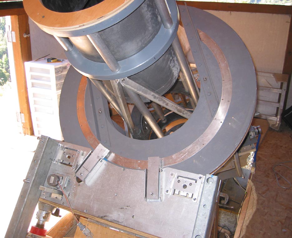
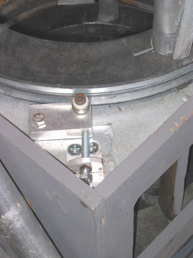 rotating tube bearing -1 of 8
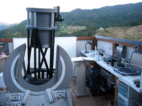
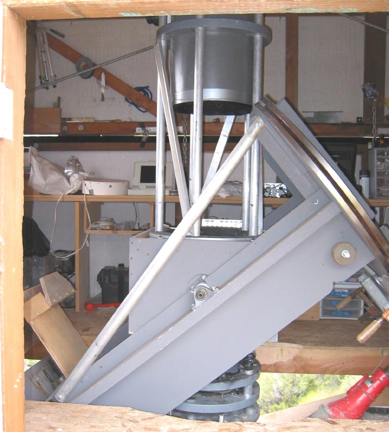 in place in the observatory
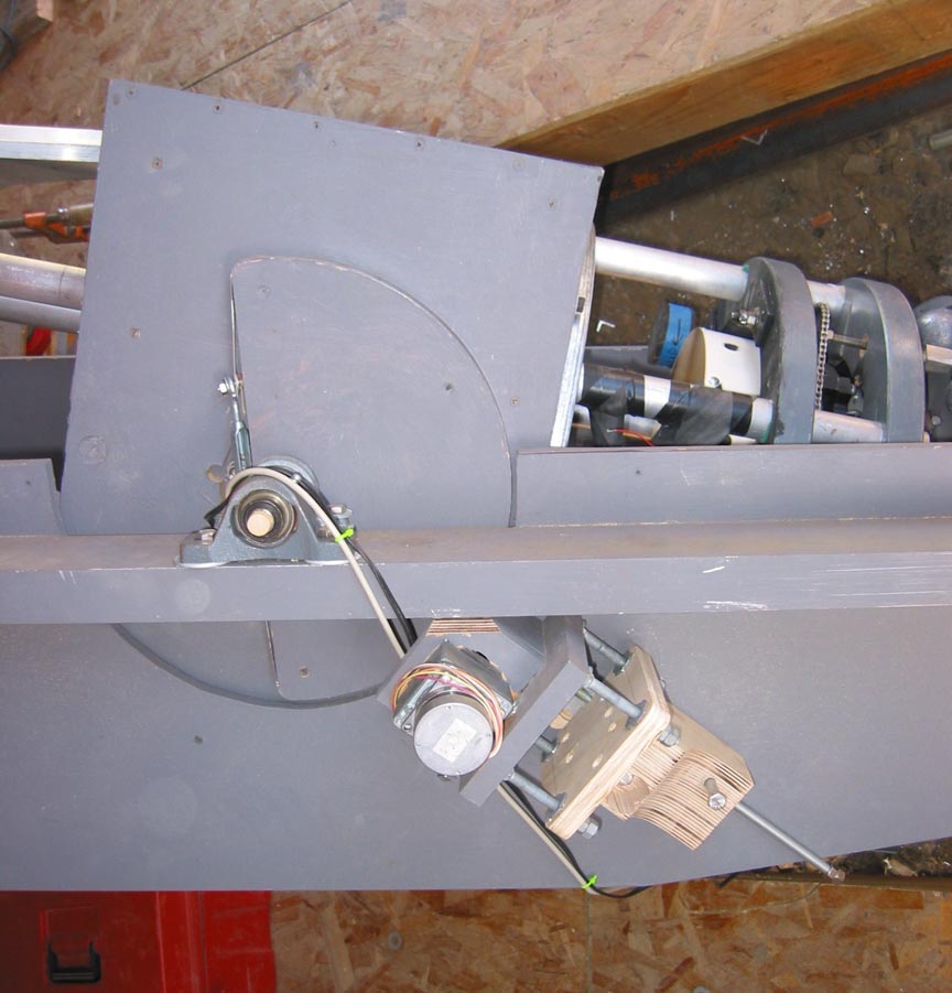 declination drive
So, how does the mount perform? Below are some unguided exposures with no software mount error correction:
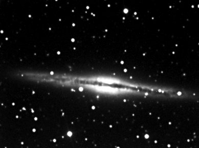
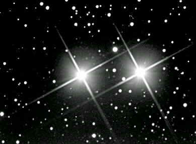
4 min NGC891 5 min Epsilon Lyrae
That is tracking. GoTo is not so good. I never have completely eliminated slipping during slews. The friction drive on the declination axis was a mistake. When I get around to it, I will replace it with a gear drive. But it is quite easy to star hop with the 9'x12' fov of the ccd camera. And visually, with a 1/2 degree eyepiece I can slew over 50 degrees and find a star in the field of view.
CONSTRUCTION:
Some numbers:
- diameter of horseshoe - 41" total gear reduction 1,496:1 (through 10" drive wheel)
- diameter of declination trunion - 15" total gear reduction 1,171:1 (through RS components 25:1 gearbox
- angle of repose: 39deg 07min 07 sec (Ukiah, California)
- non driven declination shaft diameter: 3/4" stainless
- aluminum reinforcing angle on the cradle: 2 x 2 x 1/4 aluminum
- mounting channel for the declination bearings: 1/4" x 1.75" x 4" aluminum
- tires for the drives: 1/8" x 3/4" cold rolled steel
- motor drives - Mel Bartels' stepper drive
CONSTRUCTION NOTES:
- This type of mount doesn't work very well for larger scopes unless some provision is made for getting to the eyepiece. I set the mount down into the floor of the observatory, leaving the eyepiece at a convenient height.
-
Lower right ascension axis is a live center from a woodworking lathe. This
has ball bearings and is overkill. A steel to steel plain bearing with plenty of grease
will work fine. I've changed my opinion on this point. If
the bearing cone actually moves against the cone shaped bearing surface, the
telescope yoke will tend to 'walk' out of the South bearing at temperate
latitudes. I have had none of this 'walking' with the live lathe center at
39 degrees lattitude.
- The horseshoe bearings are the drive bearings and do not really allow free rotation. Before cutting out the inner part of the horseshoe, I installed a removable steel angle with a hole at the axis of rotation. This allows me to later on locate the RA axis gives the ability to balance the axis by substituting the drive gears with a single bearing point. Neglect this detail and all is lost.
- Attaching the steel tires to the horseshoe: They must be tight so that a bubble doesn't run ahead of the drive and idler axles. I used contact cement to apply the bands and then countersunk trimhead screws to pin it in place.
ROUGH MECHANICAL ALIGNMENT OF THE AXES:
1. Aluminum tubing comes with an outside diameter that matches the id of the bearings. I use this as a temporary axle through the dec bearings. A string pulled along the ra axis running through a hole drilled through the center defines the ra axis. Use a framing square and triangulation (3-4-5 right triangle method) to square up these axes. These are the Z1 corrections in Mel Bartel's pointing model.
2. Using 2 extra bearing blocks, make an offset arm to locate an orthogonal point at a distance from the dec axis. This should be of a size that will fit into the optical tube. It will be used to align the optical axis with the mechanical axis. It must be offset so as not to block the path of the beam a laser collimator makes between the eyepiece and the main mirror.
3. Set the tube in place in the mount using the temporary aluminum dec axle with the offset arm inside the optical tube. Repull the string through the hole in the dec axle in order to align the hole with the ra axis. Mark the axle at both dec bearings with a knife blade. Remove the string and rotate the hole 90 degrees so that the laser beam can pass through.
4. Install the optics. Using the laser collimator, center the optical axis in the tube. I have parallel tubes, so I make a circle of plywood that just fits inside the tubes. I check the laser beam near the bottom and near the top, making adjustments to the main mirror and to the diagonal as necessary. If you have truss tubes (non parallel tubes), make 2 circles, one for the top and one for teh bottm. If you have a solid tube such as cardboard, I don't know what you do.
5. Using the swing arm, check the laser beam location against the mechanical axis. Adjust the OTA's dec bearing to align.
6. Slip the aluminum tube out while simultaneously slipping the permanent axles into place.